

Laser Interferometer Gravitational-Wave Observatory (LIGO)
Laser Interferometer Gravitational wave Observatory Laser Interferometer Gravitational-Wave Observatory (LIGO), INDIA is a large-scale physics experiment aiming to detect gravitational waves directly. LIGO detector is 4-km arm-length Michelson Interferometer with Fabry-Perot enhanced cavities and aims to detect the space strain sensitivity better than 10–24 Hz–1/2. LIGO-India is a collaborative project between LIGO USA and Department of Atomic Energy (DAE) (Govt. of India) for establishing an Advanced LIGO detector in India similar to that of LIGO-US (Hanford & Livingston observatories). India’s major institutes (IPR-Gandhinagar, RRCAT-Indore, DCSEM and IUCAA-Pune) are participating in installation, commissioning and operation of the Gravitational Wave detector. IPR’s Contribution: IPR is primarily responsible for the development of the following tasks: Beam Tube, BSC, HAM Chambers and associated components Vacuum Systems and its control |
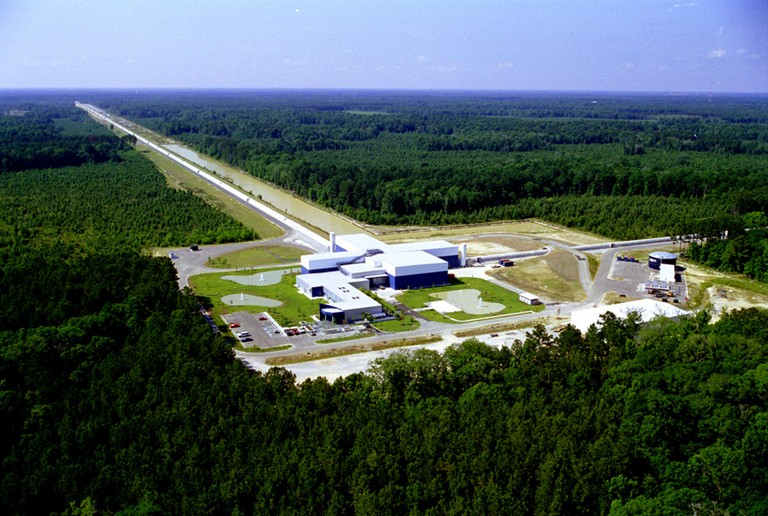
Figure: LIGO US (Livingston) Observatory (Courtesy: LIGO US)
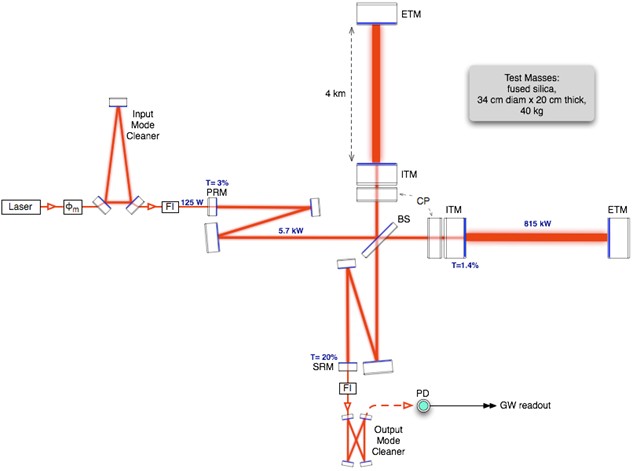
Figure: Experimental setup of LIGO (Courtesy: DCC-G1300494-V3)
Current version of the detector, termed as the Advanced LIGO (Adv-LIGO), is tailored such that the detector can cover the volume in space by a factor of 1000 compared to its earlier versions of detector termed as Initial LIGO and the Enhanced LIGO. The strain sensitivity (B.P. Abbott et. al., PRL, 116, 241103) of Adv-LIGO is measured to be h< 3.0 ´ 10–24 Hz–1/2 at 150 Hz as shown in figure.
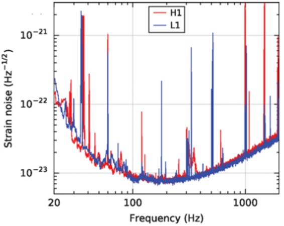
Figure: Strain sensitivity of Advanced LIGO compared at two observatories
(Hanford-H1 and Livingston-L1) at USA.
Detector configuration
LIGO-US detector mainly comprises of the following three sections:
Corner station
Mid-station
End-stations
All these three sections are interconnected with stainless steel beam tube.
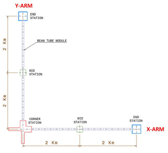
Figure: Schematic of interferometer
Vacuum System and Controls of the interferometer
LIGO detector is an integrated system of many vacuum systems and components. Each of the stations described in below figure.
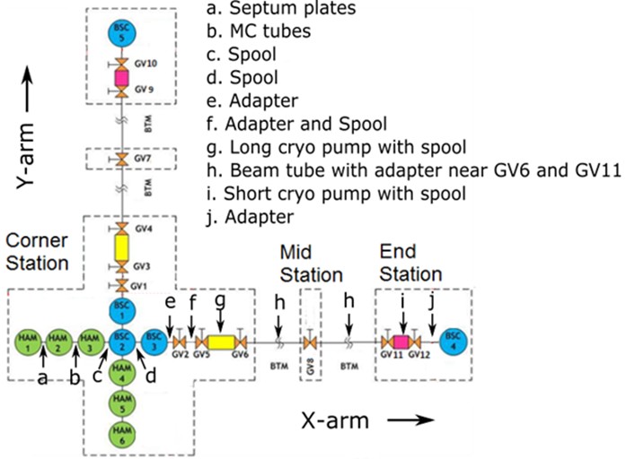
Fig. 1.4: Major vacuum components with interfaces of the interferometer along X-arm.
The interfaces are same for Y-arm.
Basic symmetric chamber (BSC) and Horizontal Access Module (HAM)
Basic Symmetric Chambers (BSC) are used to support core optical components while Horizontal Access Module (HAM) are used to house auxiliary optics (Ref. F. Matichard et. al. CQG, 32, 185003, 2015). All major optical components are housed in these two chambers. Both BSC and HAM chambers are provided with demountable cover flanges so that the servicing of the optical components could be carried out whenever needed. These chambers contain seismic isolators and alignment mechanism which support the optical elements and have internal attachment brackets. These brackets will be used to support lightweight optical components. The seals on these cover flanges shall be designed as double O-rings with a pumped annulus to reduce the gas load due to the permeability of Viton. A clean air vent and purge system shall be provided to break vacuum and maintain cleanliness of the optical components whenever a chamber is open.
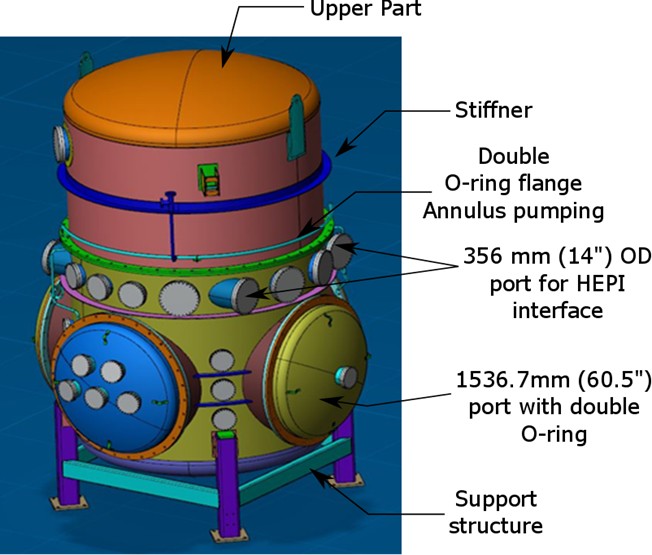
Figure: 3-D view of a BSC chamber
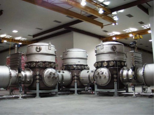
Figure: Actual picture of assembled BSC without HEPI
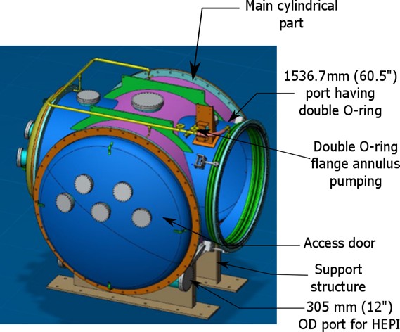
Figure: 3-D view of a HAM chamber
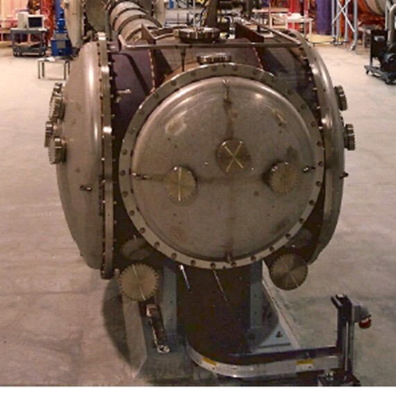
Figure: Actual picture of assembled HAM without HEPI (Courtesy: LIGO Hanford Observatory)
Beam tube
Purpose: Beam tube (annexure A) is one of the important part of the entire vacuum system. It is a cylindrical structure having 4 km length in each perpendicular direction as shown in figure.
The beam tube is kept in ultra-high vacuum so that scattering of laser beam is minimized within the Fabry-Perot cavity. Each beam tube has two (02) numbers of beam tube modules of 2.0 km length each. Each beam tube module will be fabricated from 20 m long beam tube sections of 100 numbers. These beam tube sections will be reinforced with vacuum stiffeners as well as support stiffeners. Vacuum stiffeners are provided at a separation of 750 mm distance throughout the length so that the tube can withstand pressure difference between inside and outside the tube and avoid collapsing. Support stiffeners are provided at 20 m apart to stiffen and assemble the support structure for the beam tube.
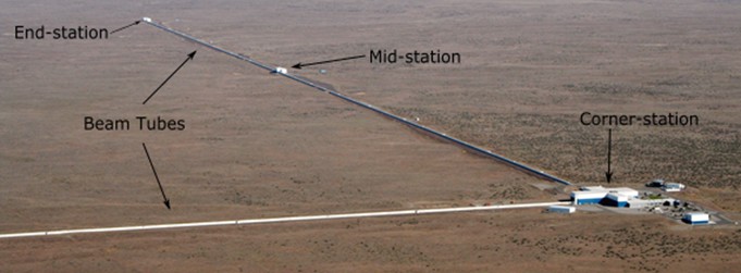
Figure: Orthogonal beam tubes at Hanford
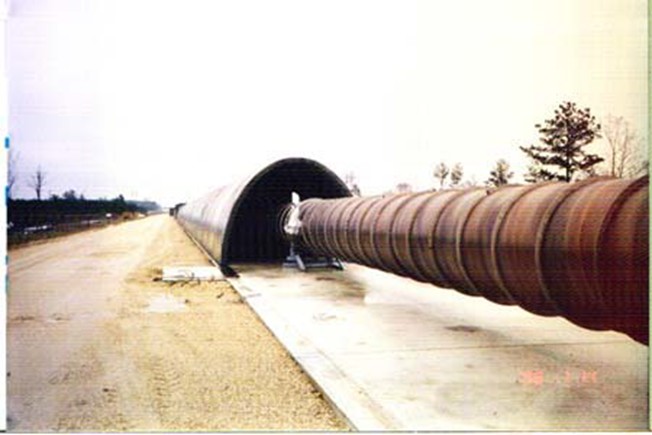
Figure: Section of beam tube at Hanford observatory
Data Acquisition and supervisory control of the Detector
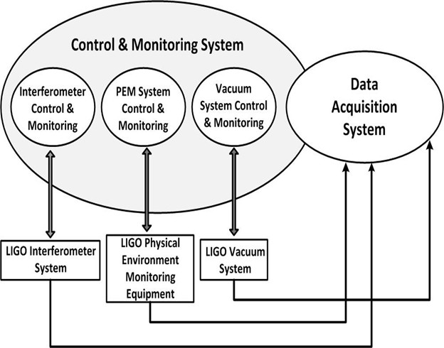
LIGO Control and Monitoring system provides electronic hardware and software for the following functions:
To remotely operate and monitor all LIGO subsystems. Communications among the various computers involved in control and monitoring activities, and connections to computing facilities.
Accurate time-stamping of collected data.
Closed loop feedback control of detector system.
PEM monitoring
Operational performance of detector
To interface to the vacuum system equipment and provide control.
Functional Requirements
Monitoring and Control:
 Supervisory control for LIGO subsystems:
Pre-stabilized Laser (PSL)
Seismic Isolation (SEI)
Suspension (SUS)
Interferometer Sensing & Control ( LSC, ASC, ALS and TSC)
Physical Environment Monitoring (PEM)
Vacuum
Feedback Control for Interferometer Sensing and Control (ISC) Subsystem. This includes Length Sensing and Control (LSC), Alignment Sensing and Control (ASC), Arm Length Stabilization (ALS), Thermal Sensing and Control (TSC) and interface to overall control of interferometer.
Data Acquisition for all subsystems
Control and Data System (CDS) Infrastructure for instrumentation and control