1.Infrared Imaging Video Bolometer (IRVB)
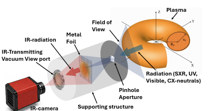
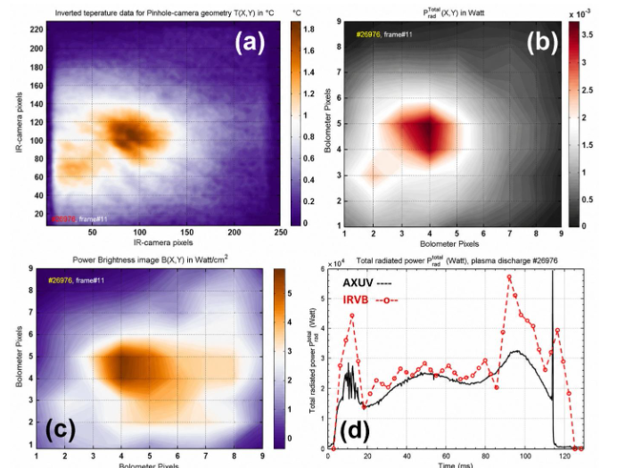
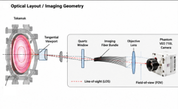
The Infrared Imaging Video Bolometer (IRVB) is an advanced plasma diagnostic technique used for measuring total radiated power loss in magnetically confined fusion plasmas. Unlike conventional bolometer systems, IRVB provides spatio-temporal two- and three-dimensional radiation profiles with improved imaging capability. The diagnostic employs a radiation-absorbing foil and an infrared camera to measure foil temperature variations induced by incident plasma radiation. IRVB offers several advantages, including immunity to electromagnetic interference through optical signal transmission, a wide spectral response, radiation hardness, a broad dynamic range, and improved tomographic reconstruction with fewer systems. These features make IRVB a promising diagnostic for present and future fusion devices. The IRVB diagnostic systems have been indigenously designed and developed for ADITYA, ADUTYA-upgrade and SST-1 tokamaks.
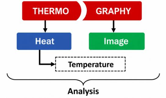
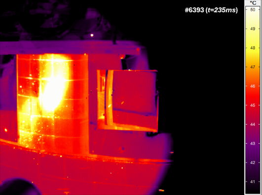
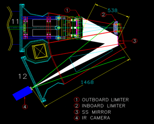
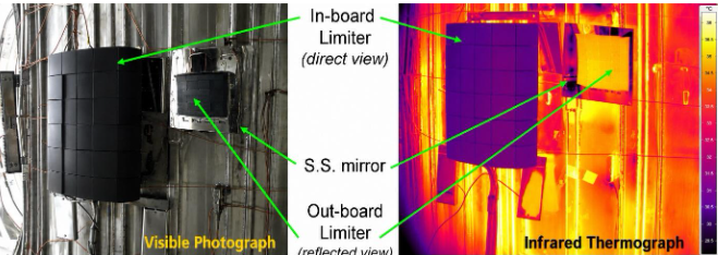
2.Infrared Thermography (IRT) of Plasma Facing Components (PFCs)Infrared Thermography (IRT) of Plasma Facing Components (PFCs), such as limiters and divertors, is an important diagnostic technique for studying plasma–wall interactions in tokamaks. One of its major advantages is the capability for real-time, remote monitoring of surface temperature over a wide field of view using an infrared camera positioned outside the vacuum vessel. The IR camera observes the PFC surfaces through infrared-transmitting vacuum viewports. Under high heat-load conditions, localized overheating can damage PFC tiles, while particles released from these surfaces may further influence plasma boundary conditions. Therefore, infrared thermographic measurements play a crucial role in monitoring surface temperatures and estimating thermal loads on PFCs. An IRT system has been deployed on both the ADITYA, ADITYA-U and SST-1 tokamaks. At present, the IRT system is extensively used for in-vessel inspection, health monitoring of limiter tiles, estimation of heat flux deposited on PFCs, heat-flux diffusion length in the Scrape-Off Layer of plasma, and various plasma physics investigations.
3.FMCW Profile reflectometry
FMCW reflectometry (K-band 18–28 GHz, Ka-band 26.5–40 GHz) is deployed at IPR on Aditya-U for edge density profiles, fluctuations, and plasma position. The system sweeps the full band in 5 μs, with data acquired at 200/245 MSps. It comprises a waveguide front-end, RF/IF back-end, trigger/timing electronics, and a frequency source driver. Advanced time-frequency and complex filtering methods process the raw beat-signal phase data. Hardware is largely indigenized, laboratory-calibrated, and fully integrated with the tokamak.
4.Anechoic Chamber and Antenna Measurement Facility
Welcome to our state-of-the-art Anechoic Chamber and Antenna Measurement Facility, designed for high-precision RF testing and antenna characterization. Our spacious 5m x 5m x 4m chamber operates optimally across a 2 GHz to 26 GHz frequency range, featuring a rigorous shielding effectiveness of -80 dB and a quietness level of -30 dB to ensure interference-free testing. The facility provides a highly stable far-field quiet zone, ranging from ~0.5 m³ at 2 GHz to ~0.15 m³ at 26 GHz. To support cutting-edge measurements, the lab is equipped with a high-performance Anritsu MS46522B Vector Network Analyzer (50 KHz to 43.5 GHz) and wideband horn antennas spanning 1.7 GHz to 40 GHz. Furthermore, a motorized single-axis antenna positioner capable of handling payloads up to 5 kg ensures accurate, automated radiation pattern measurements. This fully integrated facility is ideal for academic research, prototype testing, and advanced microwave component development.
5.ECE Radiometer Diagnostic
My research work focuses on the design, development, calibration, and characterisation of multi-channel Electron Cyclotron Emission (ECE) radiometer systems for plasma diagnostics and physics studies. These systems are used to measure the spatial and temporal evolution of electron temperature in tokamak plasmas and to investigate transport phenomena and plasma instabilities. The work involves RF and IF receiver integration, assembly of sensitive millimetre-wave components, and calibration using the Hot–Cold Dicke switch technique with an indigenously developed Silicon Carbide (SiC)-based high-temperature calibration source. The ECE radiometers developed for Aditya-U Tokamak and SST-1 Tokamak provide high-resolution plasma measurements under varied experimental conditions.
6.Microwave interferometer
A microwave Interferometer is a widely used and established system for line integrated plasma density measurement of fusion plasma. It is based on a principle of phase shift. A microwave beam will experience a phase shift while traversing through the plasma with respect to the reference arm. A change in phase is related to the change in refractive index and change is refractive index is related to the change in plasma density. Hence, by knowing the phase shift of the microwave beam coming out of the plasma will provide the information of the plasma density. Microwave interferometer system measures plasma line averaged density using millimeter wave frequency (30- 300 GHz). There are two types of techniques (1) Homodyne (2) Heterodyne. In a homodyne, only one source of frequency has been used as a probing frequency and for the down conversion of a signal coming out of the plasma. In the case of Heterodyne, two frequency sources of slightly different frequencies have been used. As a result, even in the absence of the plasma the Intermediate frequency is not zero while in the Homodyne it is zero. Both the systems have been established for the line integrated density measurement in Tokomak at IPR. A Homodyne System of 100 GHz is a multi-chord system, 6-channels for Aditya-U. Due to the multi chord, a radial profile for plasma density can be obtained. A single channel 100GHz system has established for SST Tokomak. A Heterodyne system of 140 GHz is a single channel phase-locked loop system is used for Aditya as well ad SST. A 100 GHz single channel quadrature based (IQ) heterodyne interferometer is indigenously developed and commissioned for ADITYA-U Tokomak for real-time electron density measurement during plasma discharges. Both heterodyne system gives a real time plasma density. This real time signal can be used for density control and feedback.