1.Central Control System
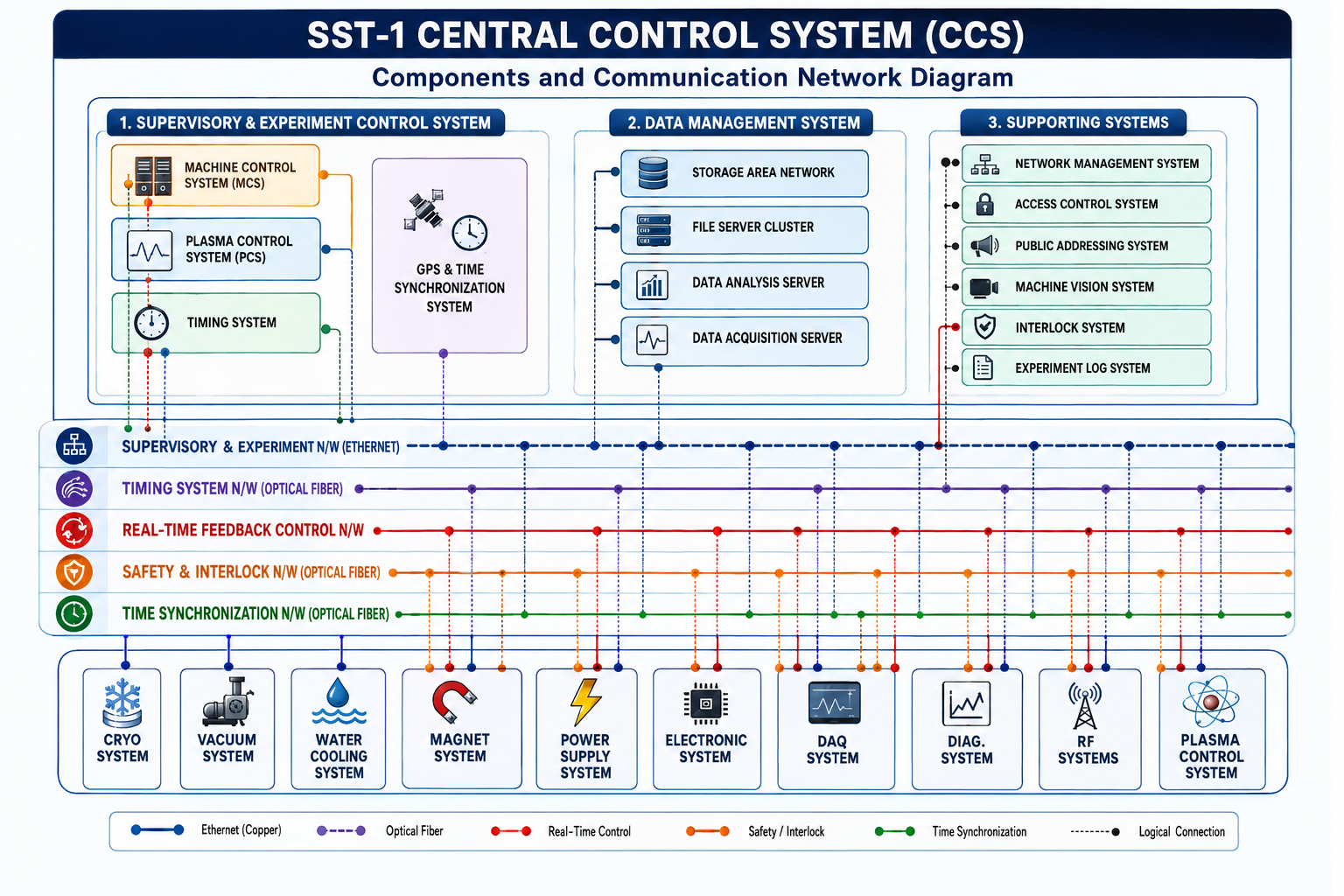
The SST-1 Central Control System (CCS) is based upon a distributed hierarchical control system. It consists of machine control, experiment discharge control, timing, and centralized data storage systems. The CCS controls and monitors various SST-1 subsystems such as water cooling, power supplies, cryogenics, vacuum, superconducting magnets, and auxiliary heating sources located remotely within the campus. All SST-1 subsystems and the CCS are connected through a high-speed 24-core fiber optic network.
2.Machine Control System
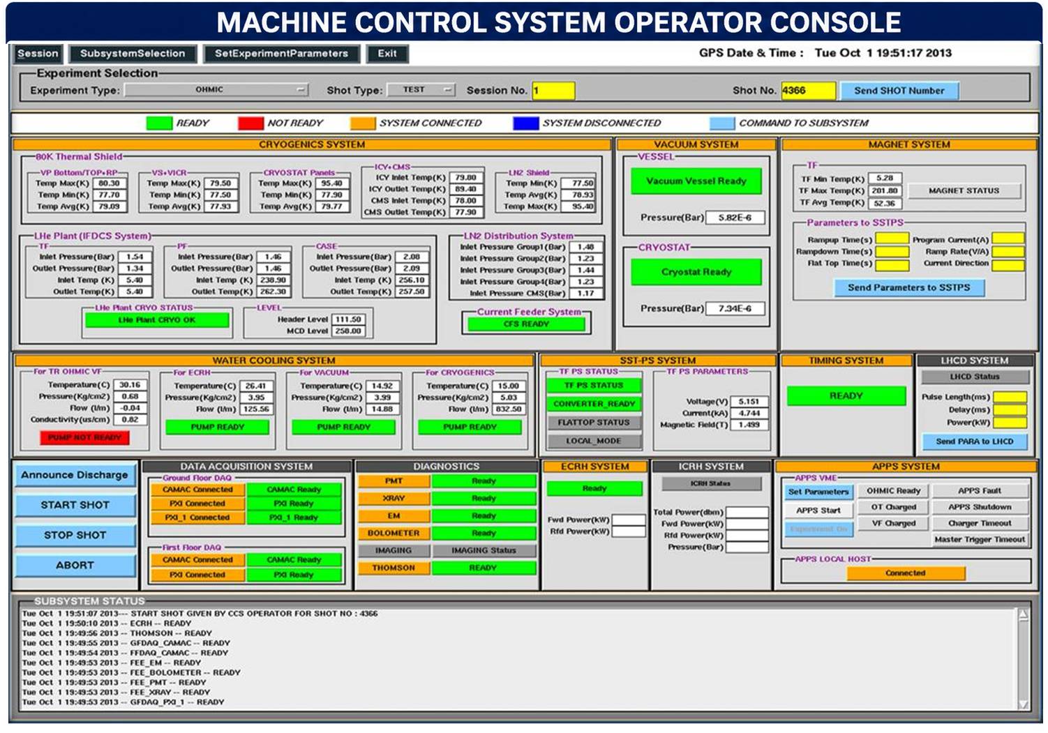
The Machine Control System (MCS) is a supervisory system that sits at the top of the CCS hierarchy and implements the CCS state diagram. MCS ensures software interlocks between the SST-1 subsystems and the CCS. Any subsystem communication failure or local error does not prohibit the execution of the MCS or CCS operation. MCS periodically monitors subsystem status and vital process parameters throughout the campaign. It also provides a platform for the Central Control operator to remotely visualize and exchange operational and experimental configuration parameters with the subsystems. MCS remains operational 24 × 7 from the commencement to the termination of the SST-1 campaign.
3.Timing System
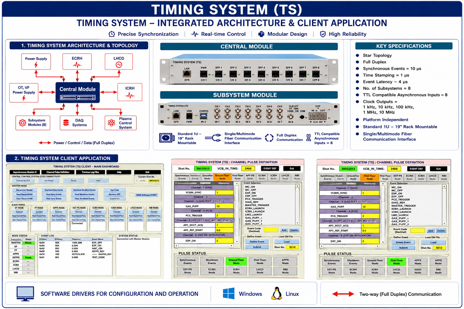
The Timing System physically consists of two types of modules: a Central Module (Master Module) and Subsystem Modules (Slave Modules). It is a real-time, event-based trigger generation and distribution system used for the synchronized operation of various heterogeneous and distributed subsystems.
Key Specifications:
Star topology, Full duplex communication, Synchronous events: 10 µs, Time stamping: 1 µs, Event latency: ~4 µs, Number of subsystems: 8, TTL compatible asynchronous inputs: 8, Clock outputs: 1 kHz, 10 kHz, 100 kHz, 1 MHz, 10 MHz, Platform independent, Standard 1U – 19" rack mountable, Single/Multimode fiber communication interface, Software drivers for configuration and operation: Windows and Linux.
4.Plasma Control System
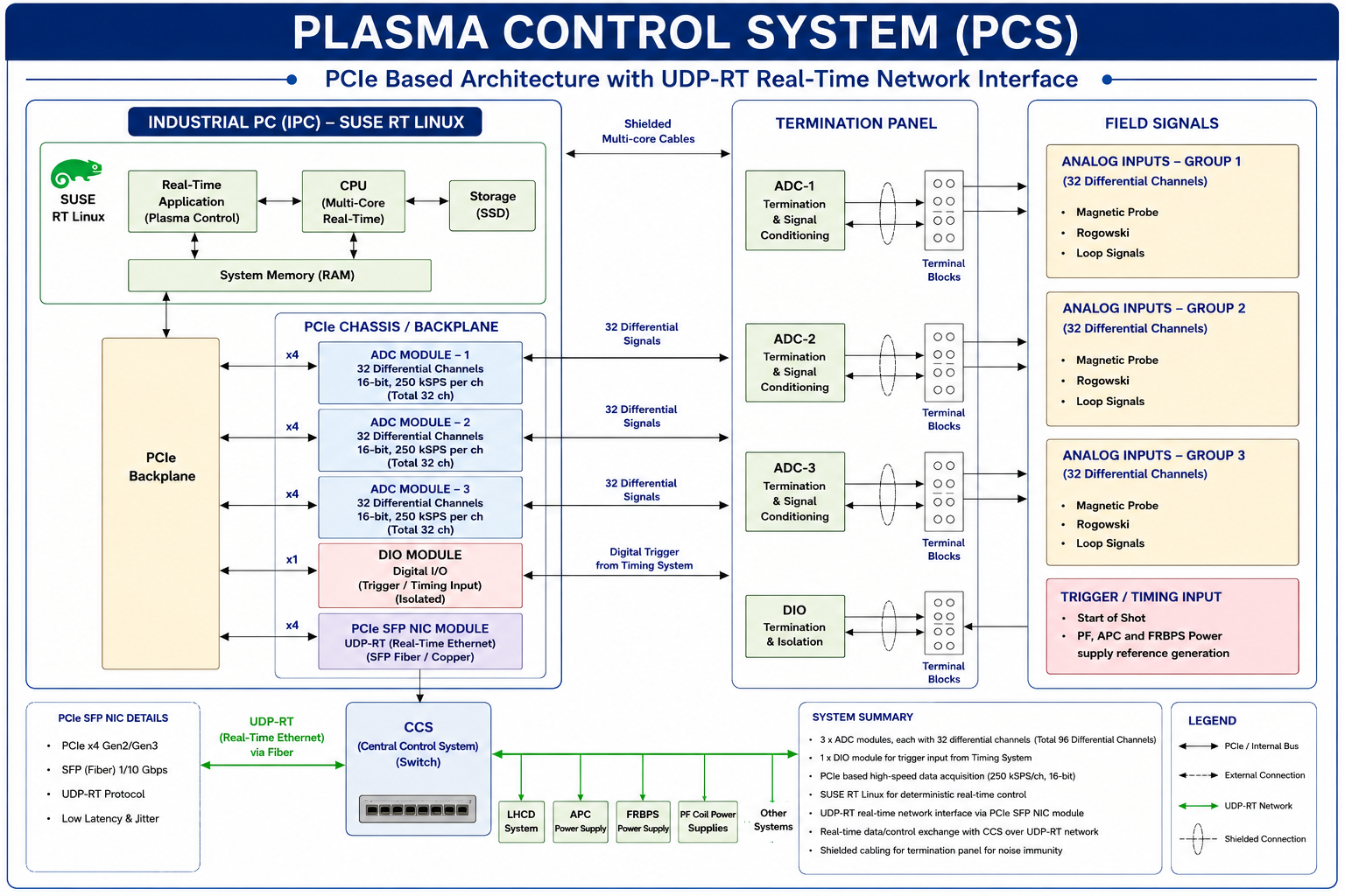
The objective of the Plasma Control System (PCS) is to control the plasma position, shape, and current in real time. The system is based on PCIe bus architecture and leverages the computational capabilities of the latest x86 multi-core processors to perform high-speed control computations with deterministic latency.
PCIe-based analog I/O cards provide the required high-speed acquisition of magnetic diagnostic signals, including magnetic probes, Rogowski coils, and loop signals, for plasma state estimation and feedback control.
The PCS communicates with actuator subsystems through a UDP Real-Time (UDP-RT) network implemented over a PCIe-based SFP network interface card operating under SUSE Real-Time Linux. The communication infrastructure provides deterministic low-latency data exchange with a round-trip time (RTT) of less than 350 μs, enabling fast and reliable control data transfer between the PCS and actuators.
5.Hardware-In-Loop
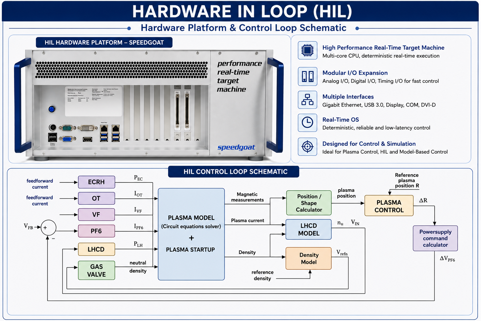
The Hardware-in-Loop (HIL) system is widely used for designing control systems. In the SST-1 Tokamak, a model-based approach is used to design the Plasma Control System (PCS), involving various subsystems that provide real-time closed-loop control of plasma position, shape, and density.
Key Specifications:
Target model execution rate: 1–10 kHz, Intel i7 (Quad Core), AI: 32, AO: 16, DIO: 64, Ethernet: 1 Gbps, Real-time operation, MATLAB–Simulink based system.