ICRH on Aditya
Steps of RF heating
1. Generating RF power.
2. Transmitting RF power
3. Course matching in vacuum
4. Conditioning of antenna, interface and Tx. Line
5. Characterization of antenna for radiation pattern
6. Launching RF power in the tokamak with Bt..
7. Radiation of RF power
8. Reaching RF power up to resonance layer
9. Absorption of RF power
10. Thermalisation of RF power in plasma
11. Heating of plasma
ICRH Heating Expt on Aditya
Aditya is a medium size tokamak with low density and low temperature circular plasma and ICRH experiments at second harmonic are carried out recently using 200 kW power at 24.8 MHz frequency.
To the best of our knowledge, direct electron heating in low temperature (<500eV) single species plasma (H2) in a medium size tokamak is not observed elsewhere.

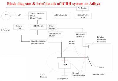
Brief description of Aditya-ICRH system
20-40 MHz frequency variable
200 kW pulsed operation for ADITYA-ICRH
50ohm coaxial copper tx lines (6" & 9") from source to Antenna (~100m)
Double Stub-PS configuration-Matching network
Directional Coupler for forward & reflected power monitoring.
Vacuum Transmission line (VTL) interfaces MN and Antenna with vacuum isolation with Aditya VV
RF related diagnostics
Rogowskii coil: antenna current
Directional coupler: forward and reflected power
VSWR probes: 20 in no. to get VSWR to find antenna impedance
Dipole probes : for RF Electric field
Magnetic loops: RF magnetic field measurements
Langmuir probes near antenna : edge density and temperature
RF Generator (20-40 MHz)
The 200 kW RF generator has following stages
MW level Oscillator
2, 20 and 200 W solid state amplifiers
2 kW triode based pre-driver amplifier
20 kW tetrode based driver amplifiers
200 kW tetrode based final stage amplifier
1.5 MW tetrode based final stage amplifier

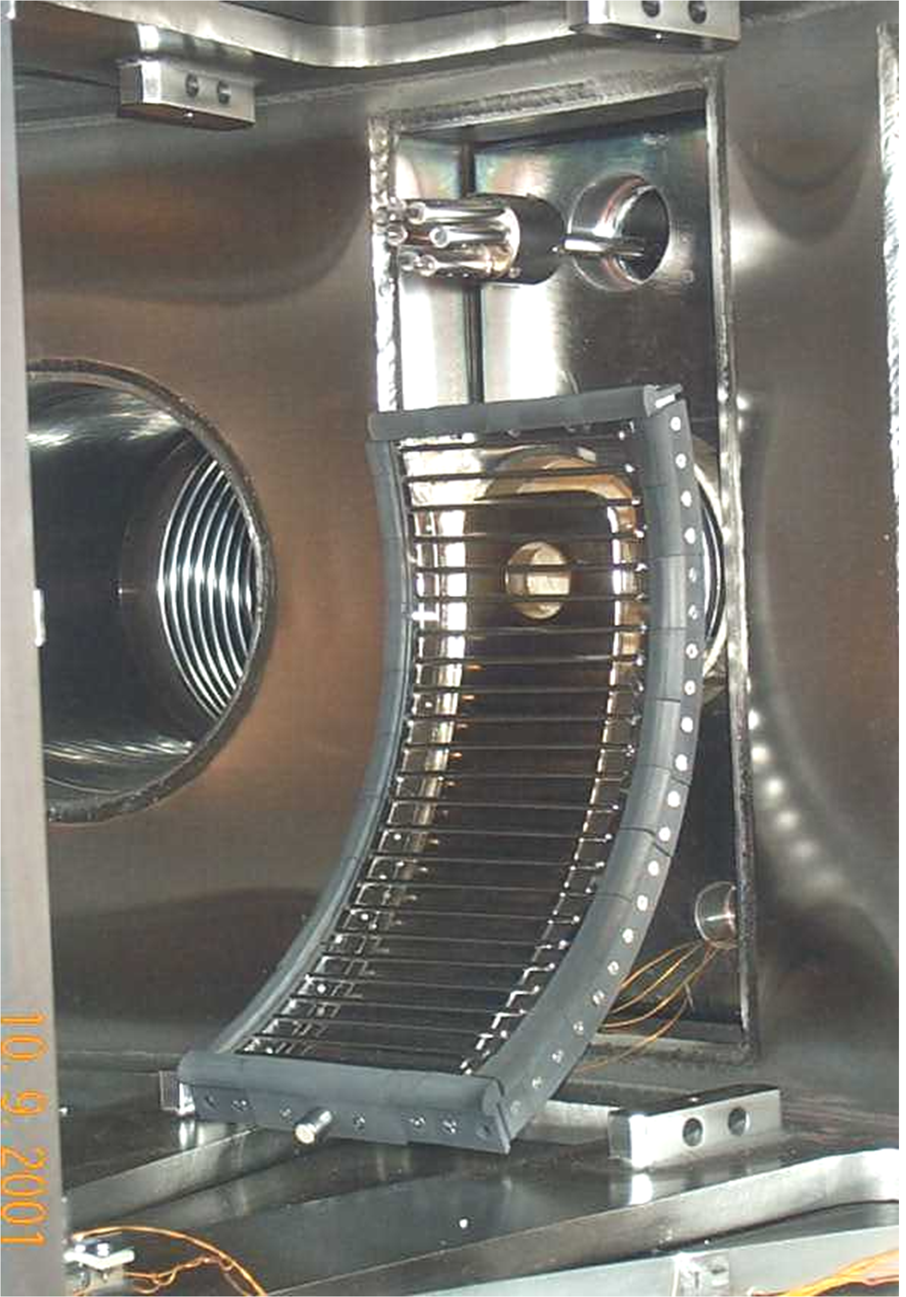
ICRH Antenna Details
Material: SS304L with graphite tiles
length (cm): 30 cm
number of straps: 1
strap width (cm): 10.0
Distance between plasma and Faraday shield (cm): 1.0 cm
Distance between plasma and antenna (cm): 3.5 cm
Distance between plasma and wall (cm): 5.8 cm from limiter
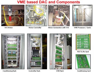
Data Acquisition and Control (DAC) system
The 200 kW RF generator has following stages
mw level Oscillator
2, 20 and 200 W solid state amplifiers
2 kW triode based pre-driver amplifier
20 kW tetrode based driver amplifiers
200 kW tetrode based final stage amplifier
1.5 MW tetrode based final stage amplifier
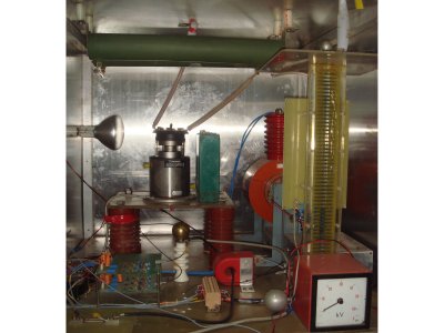
NL8900 Ignitron Crowbar System
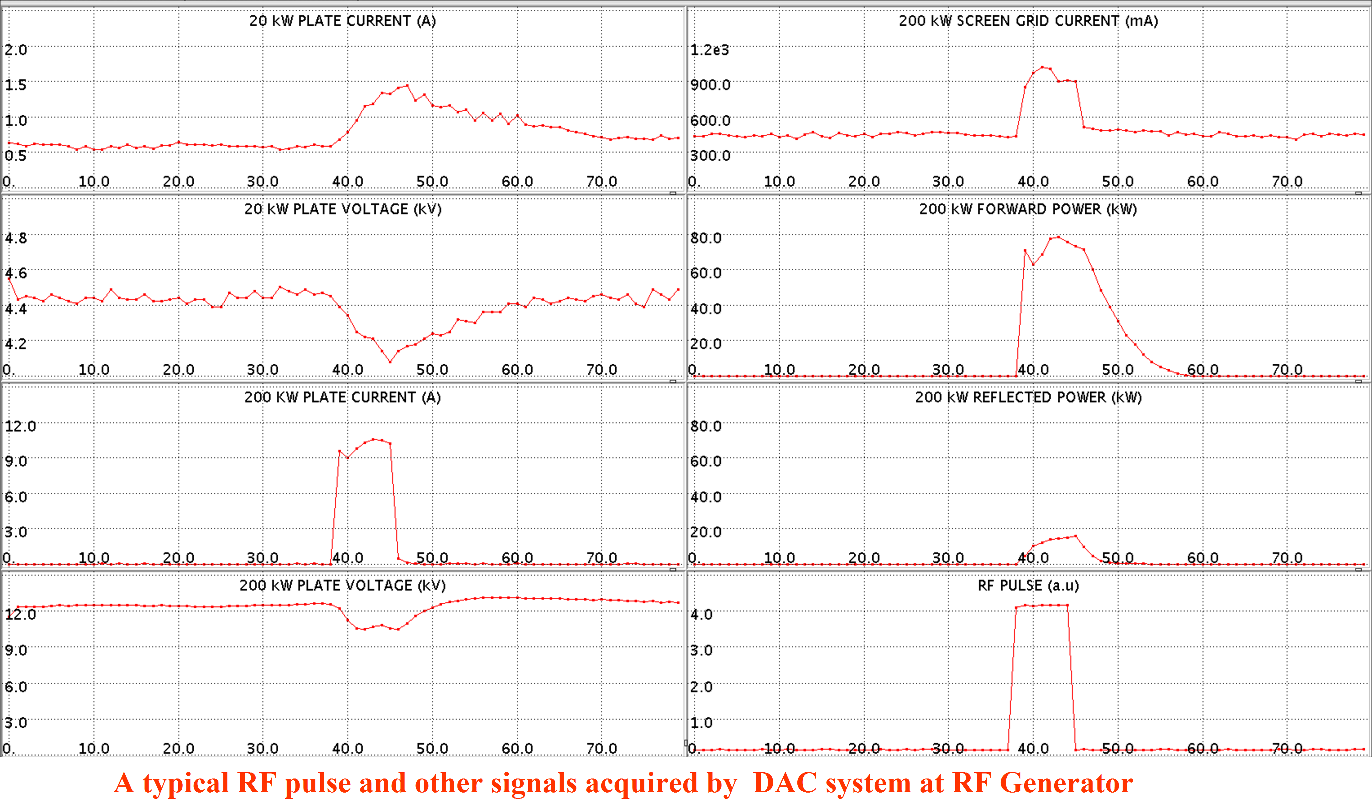
Experiments and Results
Testing of RF generator with dummy load at high power
Testing of the generator and transmission line up to vacuum interface
Testing and conditioning of vacuum interface
Matching of the antenna impedance with load impedance
Testing and conditioning of antenna for radiation in vacuum
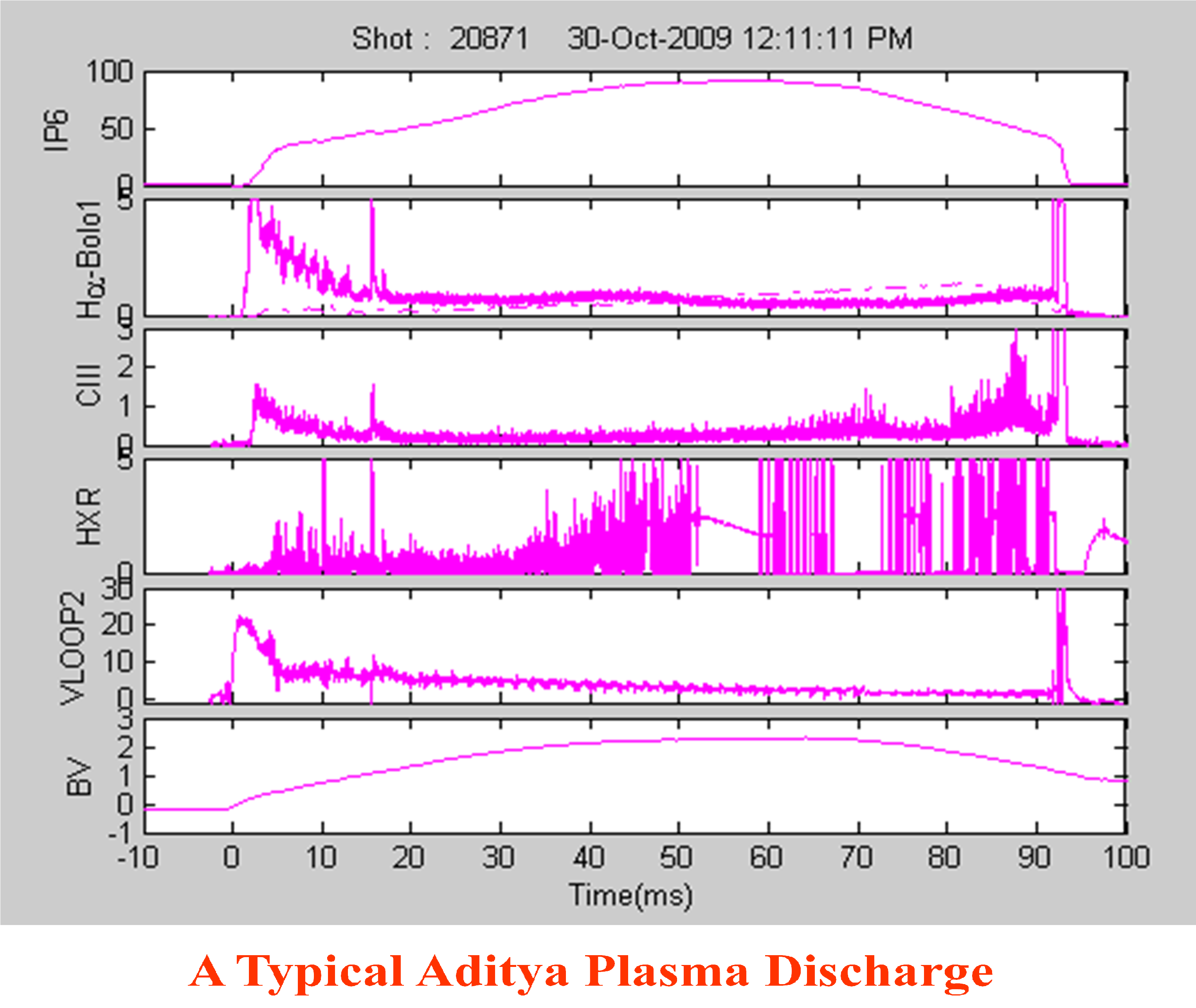
ICRH Heating at different RF power levels varying from 5 kW to 85 kW for a duration of 7-10 ms.
Bt=0.75 T, gas: H2, P: 3-5e-5 torr, Ip: 70-90 kA, t: 60-90 ms
No. of plasma shots: 109
No. of shots with rf input power: 27
Heating observed: in almost all shots
Direct Electron Heating( Kishore Mishra et al. , Direct Electron Heating Observed by Fast Waves in ICRF Range on a low density, low temperature Tokamak Aditya, AIP Conference Proceedings of the 19th Topical Conference on Radio Frequency Power in Plasmas, Newport, 1406, pp.257-260, 2011)
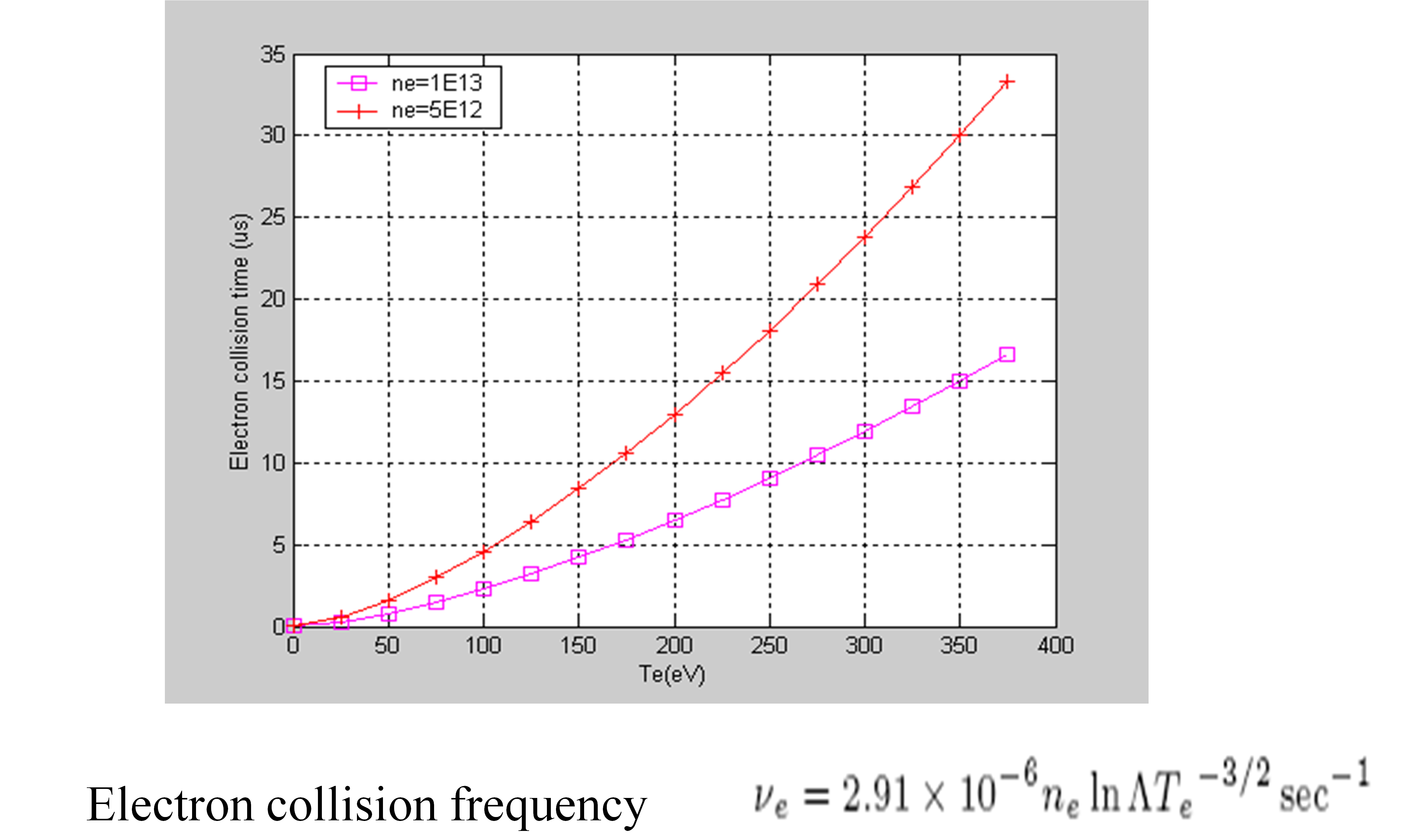
Typical time scale is electron electron collision time.
Direct electron heating is possible through NLD and TTMP
A linear dependence of electron temperature with RF power (similar to that observed on JET).
This should also give rise to ion heating
A combination of both heating method is also seen in earlier experiments. (Eriksson et al. NF V-29, p875 (1989))
In current experiment, a combination of ion heating through cyclotron resonance and direct electron heating might be happening.
Summary of preliminary experiments
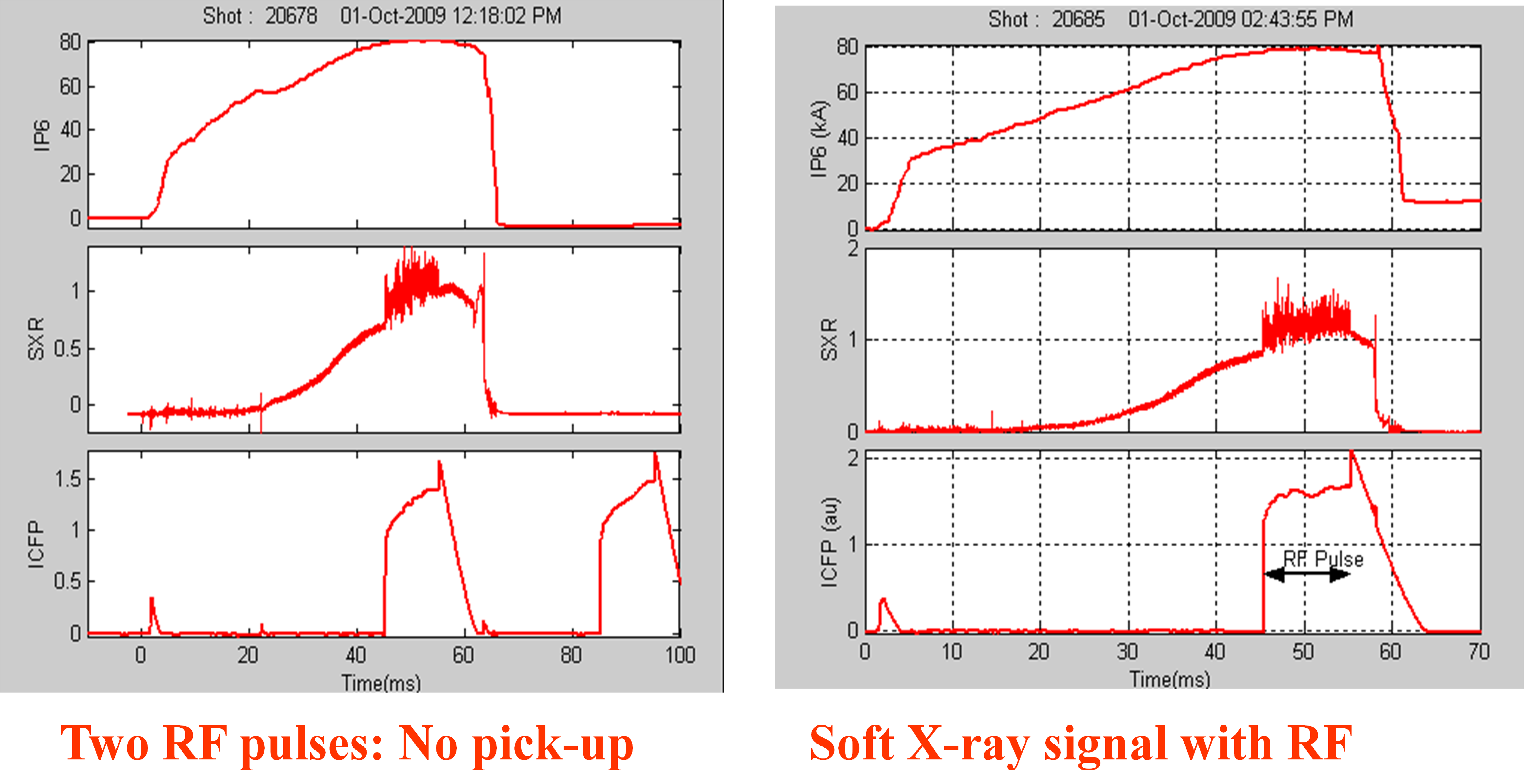
The two RF pulses given during and after the plasma shot shows that there is no RF pick-up in most of the diagnostics signals
Soft X-ray diagnostics shows that there is an immediate increase of 80-100 eV temperature rise during RF pulse of 70-80 kW power and shows that electron heating is taking place.
Diamagnetic loop signal shows that there is an increase in internal energy (0.6-1kJ to 1-1.3 kJ) of the plasma during rf pulses indicating that due to heating the stored energy of plasma increases after thermalization.
The estimated energy confinement time 2-4 ms in Ohmic phase and 3-6 ms during rf heating phase.
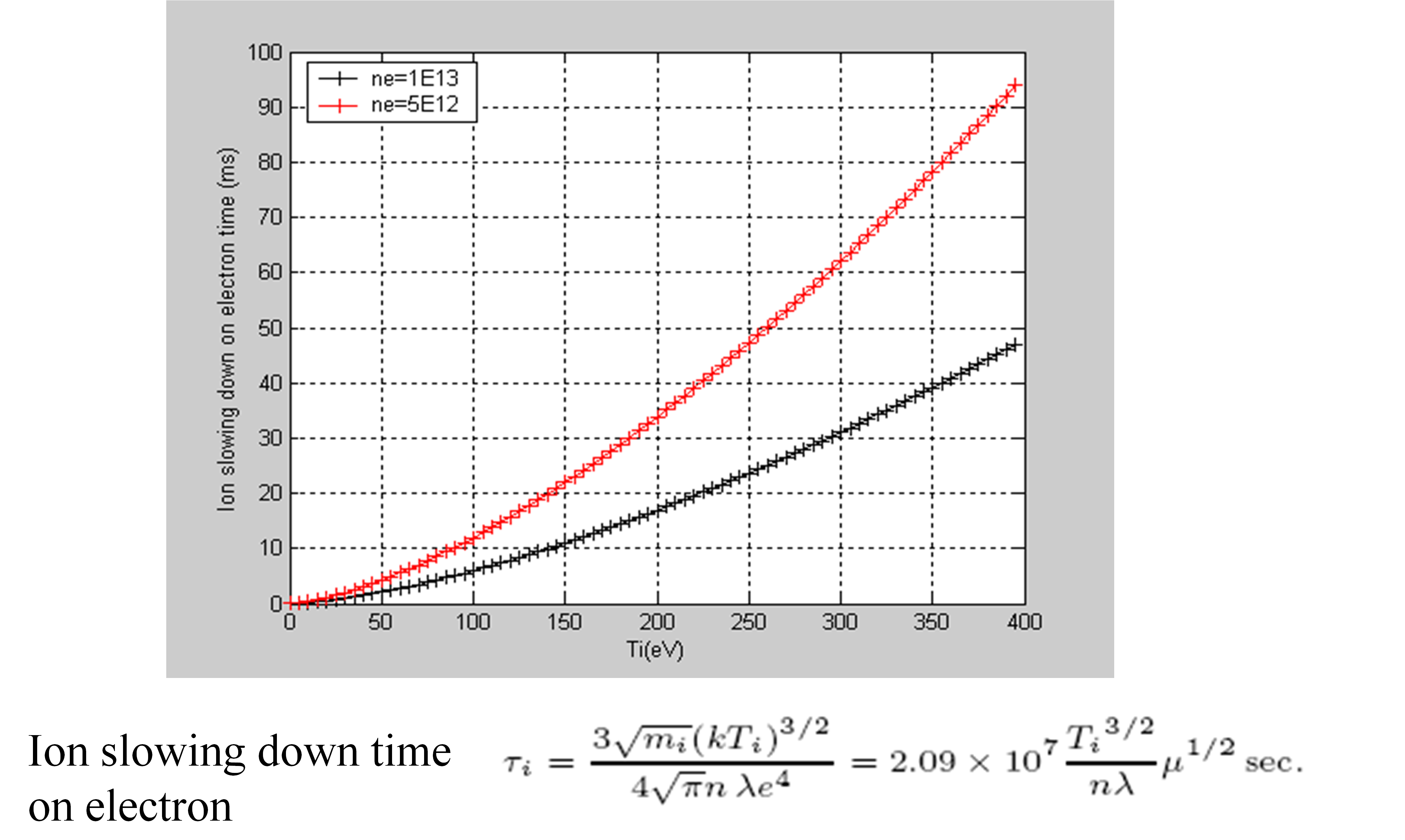
Although we have not measured ion temperature, the literature and simulation supports the idea of partial electron and ion heating. (to be established)
The spectroscopy diagnostics show that the impurity level keeps on increasing with time and do not show extra increase in impurities during RF pulse, indicates that the possibility of impurity heating is less.
Microwave interferometer signal shows that there is slight increase in the plasma density during RF pulse which is reported on many Tokamaks.
Microwave interferometer signal also shows enhancement in amplitude of MHD activities during RF pulse
Pre-ionization and current ramp-up experiments on Aditya
Why Pre-ionization is required?
To have initial no. of electrons available for highly reproducible plasma discharges
To save volts-seconds from Ohmic transformer
To have a longer plasma discharge
To produce plasma at lower loop voltages in case of super-conducting tokamaks because of design of supercoducting ohmic transformer and decrease in loop voltage due to penetration depth of cryostat
Expts. on Antenna Test Facility
Antenna test facility was upgraded in terms of magnetic field coils, magnet power supply, pressure gauges, flow meter, cooling system, compressor for gate valve, probes, RF power etc.
First Pre-ionization experiment is carried out using ion Bernstein wave antenna to prove that pre-ionization in Aditya is possible
Pressure-10**-3 to 10**-5 mBar
RF power - 1 to 15 kW, Frequency: 36.5 MHz
This gave us a confidence to do pre-ionization experiment on Aditya
Pre-ionization Experiments on Aditya
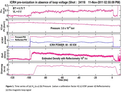
RF Power : 19 kW to140 kW at 24.8 MHz
B Toroidal : 0.075 T- 0.825 T
Antenna : Fast wave, Poloidal type
Pressure : 10-3 to 10-5 torr
Current Ramp up: up to 90 kA, 90 ms
Experiments done on Aditya
In first phase only RF breakdown plasma is produced at 24.8 MHz using a fast wave antenna without toroidal magnetic field and loop voltage.
In this phase it was observed that the breakdown is produced in antenna box in a wide range of pressures between 10-3 mBarr to 5x10⁻⁵ mBarr.
However the position of breakdown changes with pressure.
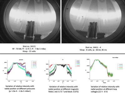
In second phase, RF plasma is produced at 24.8 MHz using a fast wave antenna, toroidal magnetic field and the developed RF system of 200 kW.
Parameters varied
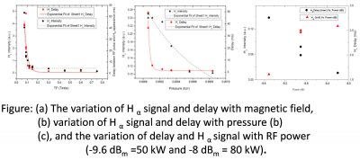
B Toroidal; 0.075 T to 0.825 T
Pressure: 8x10⁻⁴ to 3x10⁻⁵ Torr
RF Power: 19 kW to 120 kW
Minimum TF required : 900 Gauss
Minimum RF power required for PI: 19 kW
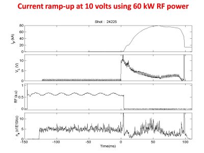
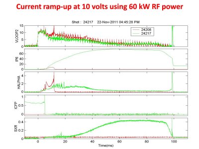
In third phase, the experiments are carried out with RF power and the full loop voltage of 22 volts. The duration of pre-ionization pulse is from -150 ms with reference to Ohmic loop voltage starting at 0 ms. In this experiment, the over-lapping time of RF power with loop voltage is varied and also the RF power is varied. The adjustment of the vertical field as well as the magnitude, duration and the frequency of the gas puff is varied to have current build up.
In fourth phase the loop voltage of Ohmic transformer is decreased by decreasing the current through the transformer due to which the available volts-sec also decrease.
In fifth phase the resistors in the ohmic transformer are changed to keep available volt-seconds constant and the current ramp-up experiments are carried out at 22V to 8 volts loop voltage.
In sixth phase the current build up experiments are carried out at fixed low loop voltage (8volts) at fixed RF power and gas pressure but with a slow rise time.
Conclusions of PI Experiment
The pre-ionization experiments are carried out in tokamak Aditya at different loop voltages, different magnetic fields to vary the position of the resonance layer and also in the wide range of pressure range for the tokamak operation in ion cyclotron frequency range.
It is observed that in presence of resonance layer the pre-ionization plasma mainly forms between antenna and the resonance layer and with proper vertical field and gas puff the current ramp up is possible even at lower loop voltages.
Although we have produced pre-ionization plasma under non-resonant conditions we are yet to produce current ramp-up which is in progress
It is expected that these results will be useful for the steady state operation of the tokamak SST-1 where the available loop voltage is less due to penetration depth of the cryostat.
There is no plasma below 0.09 T and also below 20 kW RF power
