ICRH on SST-1
Steps of RF heating
1. Generating RF power.
2. Transmitting RF power
3. Course matching in vacuum
4. Conditioning of antenna, interface and Tx. Line
5. Characterization of antenna for radiation pattern
6. Launching RF power in the tokamak with Bt..
7. Radiation of RF power
8. Reaching RF power up to resonance layer
9. Absorption of RF power
10. Thermalisation of RF power in plasma
11. Heating of plasma
Physics Experiments planned for First Phase
Second Harmonic Heating
using single transmission line with two antennas
using two transmission lines with four antennas
0,0 phasing
0, 180 phasing
Pre-ionization Experiment
Glow Discharge Cleaning/wall conditioning
RF Power Requirements for SST-1
ICRH
1 MW, 45.6 MHz (1.5 T Operation)
1 MW, 91.2 MHz (3.0 T operation)
1 MW, 20-30 MHz (minority heating at 3.0 T)

Figure: Block diagram of ICRH system on SST-1
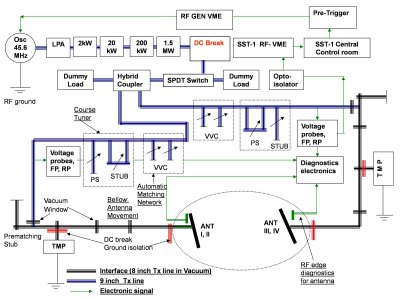
Figure: Brief architecture of ICRH system on SST-1
RF Power Requirements for SST-1
RF Generator
The 200 kW generator is used for testing transmission line and for conditioning of antenna and interface to have high power withstand capacity.
1.5 MW stage: Already developed 20-40 MHz stage will be modified and will be tuned for 45.6 MHz
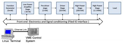
Figure-1: RF Generator systen on SST-1
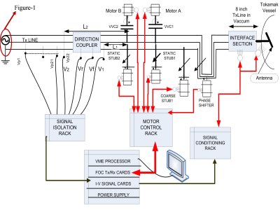
Figure-2: RF Transmission systen on SST-1
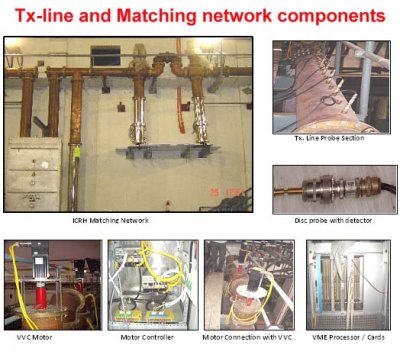
Automatic Fast Matching System using Fast Ferrite Tuner
During ICRH experiments on SST-1 tokamak, with edge-localized modes (ELM), large and fast load changes may result.
Impedance mismatch reduces (1) power delivered by tetrode-based amplifier and (2) power delivered to antenna
Hence requirement of fast impedance matching / tuning of antenna impedance to generator impedance (50 ohm).
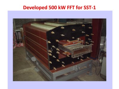
Fast ferrite tuner for SST-1 tokamak
Specifications:
Frequency range: 20 MHz - 91 MHz
Input power = 1.0 MW
Return loss > -25 dB
Insertion loss <- 0.1 dB
Mismatch region ? = 0.65 with all phases.
Response time: 6 ms
Tested with VNA and then with 1 kW rf generator with random load
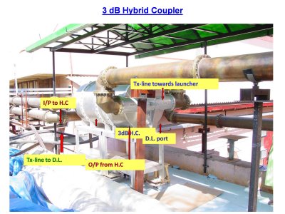
3 dB Hybrid Coupler
Specification of Hybrid Coupler: To divide power equally in two arms
4 port device, Modular setup, F: 22 MHz - 25 MHz, 45.6 MHz & 91.2 MHz
Power handling capability: 1.5 MW CW, Type: Coaxial line, EIA 9 3/16" 50 Ohm
Coupling: 3 dB ? 0.07dB, VSWR: > 26 dB, IL: 0.09 dB (Max.), Isolation >35 dB
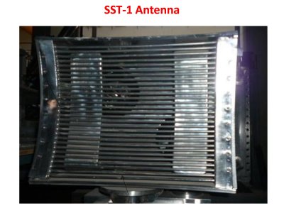
SST-1 Antenna
Made up of SS304L. One antenna box contains two antennae. Each antenna is shorted strip-line. Each antenna will carry RF power of 250kW.
Antenna is shielded from the plasma by 30 no. of Faraday shields in a single column.
Graphite tiles has to be fixed on all four sides of the box from inside
Cooling connections are done during assembly
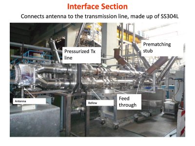
Diagnostics for ICRH-SST1
A. Antenna Edge Plasma Diagnostics:
To measure Plasma edge parameters like
Electron density (ne)
Electron Temperature(Te)
Electric Field (E? & Ef)
A probe hat consists of Langmuir probe,Electric dipole,magnetic loop,
near of RF launchers, as coupling of RF waves is greatly dependent on the plasma edge conditions. The probe hats have linear movement mechanism (~5 cm)
B. RF Diagnostics:
To measure RF parameters
Antenna current: Rogowski coil
VSWR: VSWR probe section
Forward & reflected power: Directional coupler
Antenna tiles temperature: thermocouple
C.Interface Diagnostics:
Interface Pressure: ionization gauges
Interface Arc: Arc detectors
Interface cooling & interlock: flow meters & switch
Interface temperature: calorimetric
D.High Energy ion detection system on minority heating:
Data Acquisition and Control System
The DAC is based upon two real time VME systems.
First VME is dedicated for RF generator
Second VME communicates with SST-1 central control system and is for automatic matching system
Complete software and front end electronics is designed, developed and is working well
Status of ICRH system on SST-1
Both arms of transmission line, interface and antenna is commissioned on SST-1
The ultimate vacuum in achieved in interface after sufficient baking
The transmission line, interface and antenna is conditioned with short RF pulses starting from low power to high power up to 140 kW
With 1.2 kGauss toroidal magnetic field and right pressure of H2 gas, the breakdown is produced and it is observed that it spreads toroidally in the vacuum vessel
Second antenna and interface is commissioned on SST-1 and tested with 200 kW
