1 High Heat Flux Test Facility
Leaflets:
Contact: Mr. Sunil M. Belsare
(belsare AT ipr.res.in)
Ph.No: +91-79-2396 4015/4420
Contact: Mr.Rajamannar Swamy
(rajamannar AT ipr.res.in)
Ph.No: +91-79-2396 4420
HHF introduction:-
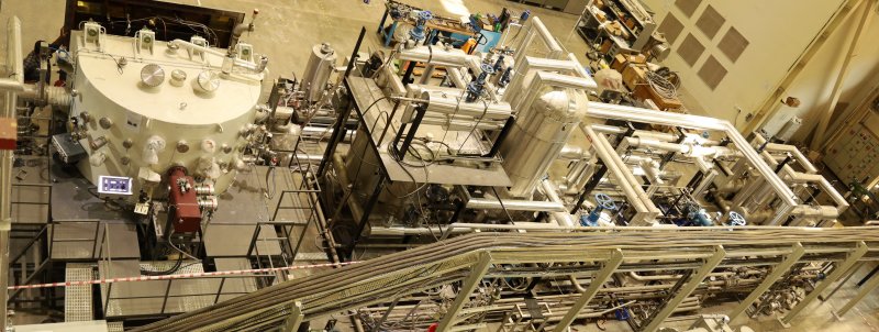
High heat flux test facilities of various kind are being used worldwide to investigate the performance of plasma facing materials/ mock-ups/ components under estimated thermal load conditions in various plasma fusion devices. The high heat flux test facility has been set-up at IPR to perform thermal load testing of plasma facing materials/ mock-ups /components. It is equipped with a high power cylindrical electron beam used as heat source having maximum beam power of 200 kW @45kV having static and dynamic deflection angle of +/- 25 and +/-10 degree respectively that allow testing of large size components up to 2m (W) x 1.2m (H)surface area. The beam can be operated to simulate quasi-steady state as well as transient heat loads over test objects by either rastering it over test object at high frequency (up to 10kHz) or by operating it in pulsed mode (t > 1ms). The electron beam is horizontally mounted on a large volume (~ 7 m3) D-shaped double-walled vacuum chamber with target-handling facility that can handle large sized test objects weighing up to 2 ton. High pressure Water loop system, High pressure Helium loop system, Thermal diagnostic systems and Data Acquisition & Control system will be integrated with the facility for testing water cooled as well as helium cooled plasma facing components.
Features of HHF test facility
 Simulation of ITER and DEMO specific thermal loads on plasma facing components viz. Divertors and First Wall Components.
 Thermal fatigue testing of divertor and first wall modules.
 ELMs simulation experiments for materials testing.
 High Pressure High Temperature Water and Helium coolant loops.
 Validation of materials, designs and joining process on small size test mock-ups as well as full-size fabricated components.
 Vacuum chamber having more than 50 diagnostic ports with several sophisticated thermal and calorimetric diagnostics.
 Sophisticated Data Acquisition & Control system.
1 Vacuum Chamber
2 Electron Beam System
3 High pressure high temperature water circulation system HPHT-WCS
4 High temperature High Pressure Helium cooling system for high heat flux testing
1. Vacuum Chamber
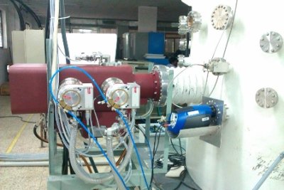
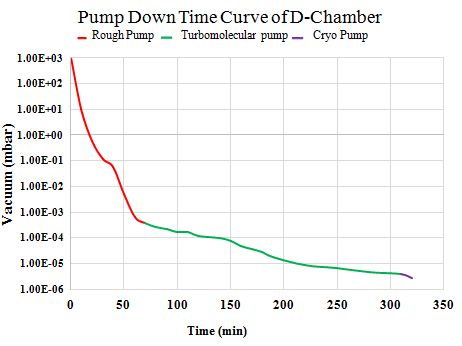
A D-shaped configuration type vacuum chamber has been successfully fabricated and commissioned along with the electron gun for high heat flux testing. The electron gun is projected horizontally from backside and will be supported separately with a separate arrangement. The dimensions of the chamber are - diameter 2.4 m, height 1.5 m with double wall cooling system to accommodate full-scale mock-up of size: 2.0m x 1.2m x 0.8 m. The mounting of test mock - up / components are carried out on target handling arrangement which is also a front door for closing the chamber. The door has feed-throughs for connecting high pressure systems to the test mock -ups. The position of diagnostic ports are designed in such a way that all the ports can view the total area of the mock - up such that the data at any point on the mock - up can be easily done through the diagnostic devices. The salient features of the vacuum chamber are that small scale to full scale testing of mock ups / components can be done. The ~7m3 D-shaped vacuum chamber has over 50 ports for diagnostics and views of the target and 4500 l/s (N2 gas) cryo pump and 1900 l/s (N2 gas) turbo molecular pumps are used for creating vacuum pressure of 10-6 mbar.
Parameters:-
Roughing Pumps: 5 Nos.
Rotary pump (3 NOs) : 65m3/h.
Rotary pump (1 NOs) : 20m3/h.
Root pump (1 NOs): 150m3/h
High Vacuum Pumps: 3 Nos.
Turbo Molecular Pump: 1900 l/s for N2
Cryo Pump: 4000 l/s for N2.
LN2 Cryopump : 1000 l/s for N2
(Indigenously developed by Cryopump division of IPR)
Ultimate vacuum of the Chamber: 1 x10⁻⁶ mbar.
Total volume: 7m3
Target Handling System:-
Component size: 2.0m x 1.2m x 0.8m of Weight up to 2000 kg
Beam Scanning Angle achieved : +/- 33 deg
Heating area : 2m x 1.2m
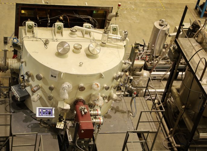
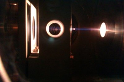
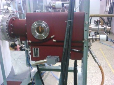
2. Electron Beam System High power electron beam gun EH 300 V manufactured by M/s Von Ardenne, Germany, has been installed, commissioned and tested successfully. The maximum beam power is 200kW, beam power is controlled by a patented VARIOCATHODE. Power below 20% are achieved by a reduction of the cathode temperature. The acceleration voltage is variable in the range between few kV and 45 kV, whereas the maximum power is only reached at acceleration voltages of 45 kV. To enable the simulations of very short event types in the millisecond range, a high voltage pulse mode has been integrated. In this case, the beam power is controlled by a predefined cathode position, and a pulse repetition rate of up to 10 kHz can be defined. A system of two magnetic lenses is used to focus the beam. By additionally optimizing the process chamber pressure, the electron beam diameter can be reduced to reasonable size. The total deflection angle of the EB is limited by the dimensions of the process chamber to +/- 33 degree. The process chamber and the two vacuum chambers of the EB-gun are effectively separated. This enables very flexible pressure optimizations and additionally access to single components with short process interruption times. EB Gun Parameters:
|
|
3. High pressure high temperature water circulation system HPHT-WCS
The high pressure high temperature water circulation system (HPHT-WCS) has been designed to cool down the test mock-up which is connected to the HHF test facility. The test mock-up connected to the water circulation loop has a maximum heat load of 210 kW. In this test loop de-mineralized water (D.M water) is used as a working medium and system can operate in the pressure range of 5 bar to 60 bar and the temperature range of 25 degree C to 160 degree C with a maximum flow rate of 300 LPM. Inert gas pressurization method is used to pressurize the DM water in the pressure vessel using nitrogen. The nitrogen source (bank of nitrogen cylinders) connected with pressure vessel and a pneumatic pressure regulator controls flow of nitrogen in to the pressure vessel. The data acquisition system (DAS) with instruments is installed along with the test facility to record and control the test parameters pressure, temperature and flow rate. The test loop is designed as per relevant safety standards.
The major components of the test loop are reservoir tank, two positive displacement pumps with motor, pressure vessel with accessories, bank of nitrogen cylinders, two booster pumps with variable frequency drive, vortex type flow meter, heater bank, cooling unit, different types of valves at various locations, safety devices, pressure, temperature, level and other sensors/ indicator/transmitters with controllers. A detailed engineering design of various components like pressure vessel, heat exchanger, cooling tower along with thermo hydraulic analysis has been carried out.
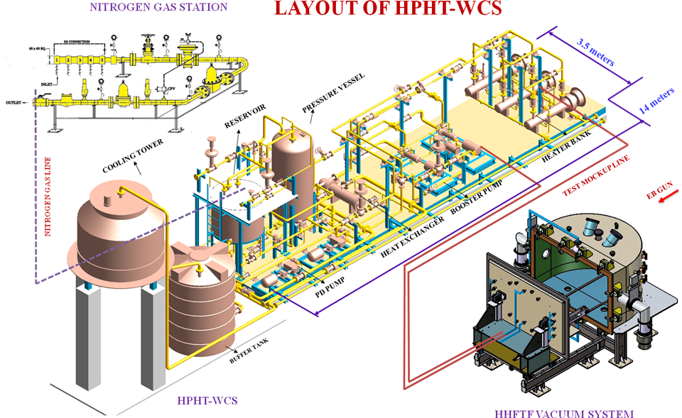
Figure: Isometric view of High Pressure High Temperature Water Circulation System (HPHT-WCS)
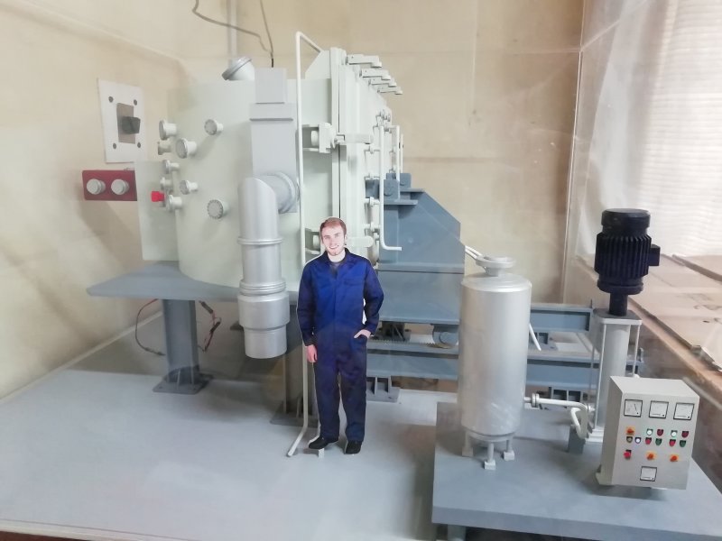
Small Scale Model of HHFTF
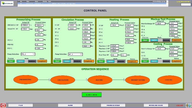
Snap shot of control Panel
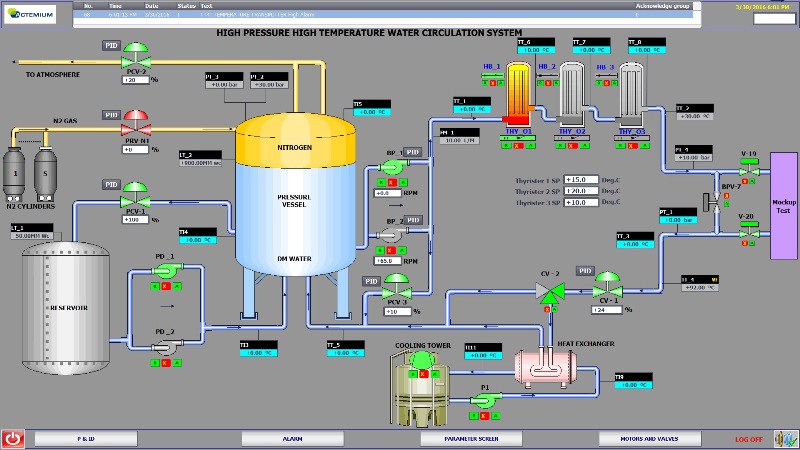
Snap shot of HPHTCS software
4. Integration of EHCL with Helium Cooled Target handling System (HTS):-
Experimental Helium Cooling Loop (EHCL) of Fusion Blanket Division is integrated with upgraded HHFTF for supplying high-pressure, high temperature helium gas operated at maximum inlet temperature of 400ºC, maximum Inlet pressure of 80 bar and maximum flow rate of 400 g /s. Supply and returns lines are routed from EHCL up to HTS and are connected to pipe header assembly.


